Increasing a Microscope’s Effective Field of View via Overlapped Imaging and Deep Learning Classification
Xing Yao1, Vinayak Pathak1, Haoran Xi2, Kevin C. Zhou 3, Amey Chaware 3, Colin Cooke 3 , Kanghyun Kim1 , Shiqi Xu1, Yuting Li1, Tim Dunn 4 and Roarke Horstmeyer1,3
1: Department of Biomedical Engineering, Duke University, Durham NC, USA.
2: Department of Computer Science, Duke University, Durham NC, USA.
3: Department of Electrical and Computer Engineering, Duke University, Durham NC, USA
4: Duke Forge, Duke University, Durham, NC 27708 USA
Links to Paper Code and Dataset
Abstract
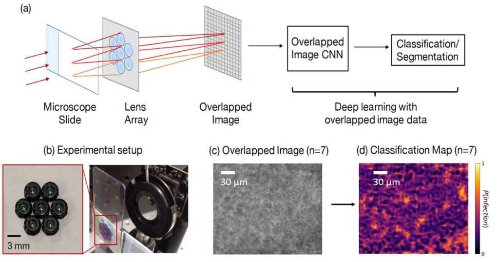
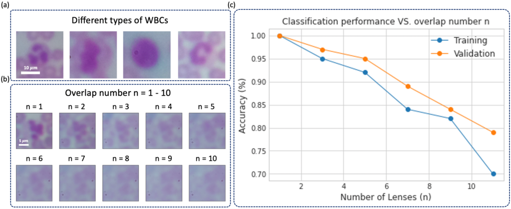
It is challenging and time-consuming for trained technicians to visually examine blood smears to reach a diagnostic conclusion. A good example is the identification of infection with the malaria parasite, which can take upwards of ten minutes of concentrated searching per patient. While digital microscope image capture and analysis software can help automate this process, the limited field-of-view of high-resolution objective lenses still makes this a challenging task. Here, we present an imaging system that simultaneously captures multiple images across a large effective field-of-view, overlaps these images onto a common detector, and then automatically classifies the overlapped image’s contents to increase malaria parasite detection throughput. We show that malaria parasite classification accuracy decreases approximately linearly as a function of image overlap number. For our experimentally captured data, we observe a classification accuracy decrease from approximately 0.9-0.95 for a single non-overlapped image, to approximately 0.7 for a 7X overlapped image. We demonstrate that it is possible to overlap seven unique images onto a common sensor within a compact, inexpensive microscope hardware design, utilizing off-the-shelf micro-objective lenses, while still offering relatively accurate classification of the presence or absence of the parasite within the acquired dataset. With additional development, this approach may offer a 7X potential speed-up for automated disease diagnosis from microscope image data over large fields-of-view.
Overview:
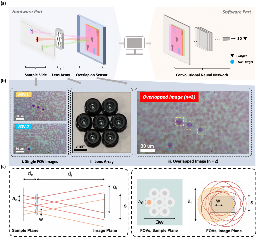
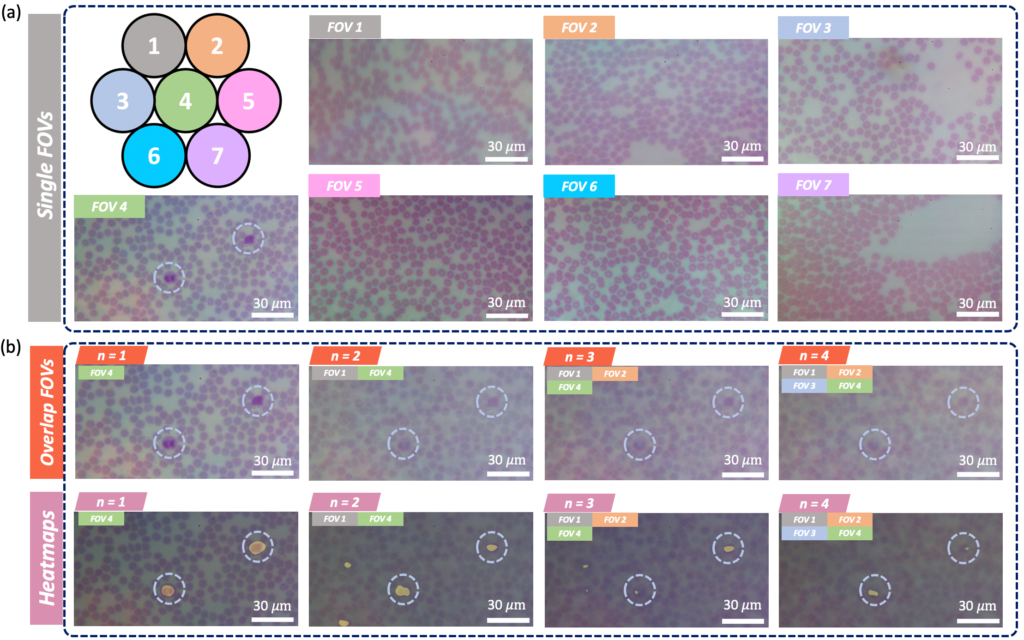
FOVs are illuminated by LEDs and then imaged onto a common sensor through a
multi-lens array to form an overlapped image. A CNN-based post processing framework is then employed to identify target features or objects within the overlapped image. (b)2 single-FOV images (FOV1, FOV2) of a hematological sample, ii. the lens array,
and iii. the overlapped image (n = 2) for WBC counting task. (c) Overlapped imaging
setup. Left: imaging geometry with sample imaged by three lenses and overlapped on a single image sensor. Right: FOVs of 7 lenses marked as gray circles at the sample
plane, where FOVs of diameter a0 are separated by lens pitch w and do not overlap. At
the image plane, FOVs denoted by red circles of diameter ai have significant overlap.
Marked variables are listed in Table below .
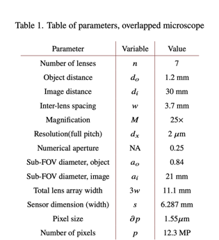 table
table
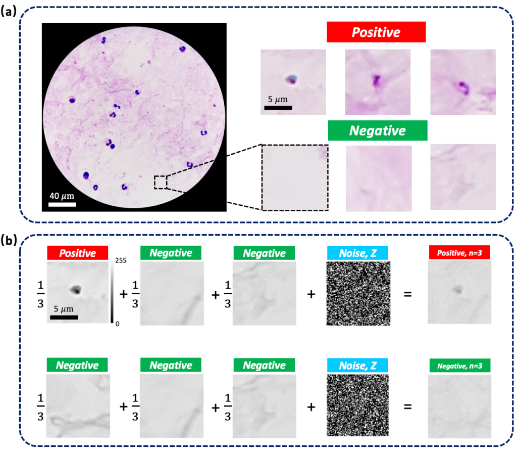
conditions
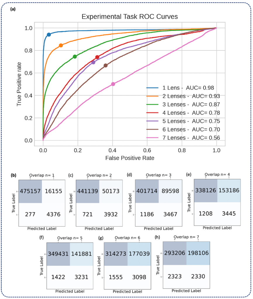
reported as ROC curves (a) and confusion matrices (b-h) aggregated under various
degrees of overlap (n = 1-7). Solid circles on each ROC curve denote the true positive
rate (TPR) and false positive rate (FPR) corresponding to the threshold at which the
confusion matrices were calculated, which was chosen to maximize the geometric mean
of TPR and true negative rate (TNR)
Code and Data
Please click below for accessing Code and Data

